Continuous Variable Transmissions CVT |
||
Why the CVTThe idea of a transmission used in most production cars today is limited to physics that are based upon a basic 10 speed bicycle. The little gears are used to help you get going, and the bigger gears deliver more power. Even things like torque and horse power apply with these mechanics. The clear issue is that a non-variable transmission, of fixed ratios, limits the exact mix of power input to power translation. This means the engine has work harder or struggles depending on the driving conditions. A great alternative are CVT's. These transmissions do not rely on gears at all, but rather conical construction or dynamic gearing. What then becomes possible are very exact mixtures of power in and power out that can be adjusted given various driving scenarios. Regardless of the uphill grade, a CVT can automatically adjust gear ratios to suit the exact incline plus vehicle load to match optimum torque derived from the engine. There are many examples of these types of transmissions being used currently. In fact, CVT's are not a new idea at all. They were invented decades ago and have been used in various motoring applications since the 1950's. There are even manufacturers today that use the design simply because it delivers greater efficiency, but they program the thing to act like a manual transmission. Most scooters that you see on the road use CVT's and there are a whole raft of farm equipment and ride on mowers and outdoor automotive products that rely on CVT's to keep these types of vehicle supplied with exact gearing to match conditions. The next logical step in the evolution is to bring these benefits into the mass market. Not only can they be more effective as transmissions compared to the industry standard, but they also have fewer parts and are cheaper to produce. The Warko CVTAnother variation of the CVT that calls for attention has been designed by an Australian under the banner of Warko.
Furthermore, the addition of moremoving parts also means that therre is increased friction and therefore increased heat geerated. Due to the nature of physics, it is impossible to completely eliminate heat during a mechanical transfer of energy such as this. However, since the load is shared between mutliple points of contact, the load is shared amongst the component parts. In all likelihood, this system would produce very little overall heat from friction. This would also indicate that the wear on the parts will be lower than that of a traditional transmission or oven a Toroidal transmission. |
 Pictured above is a Toroidal or roller-based CVT. The general principal is based on creating greater gear ratios by manipulating the diameter of the contact areas between the main rotor and the drive unit. Some of the challenges this design face are akin to the challenges that a traditional transmission are faced with. Namely, the friction cause from direct contact causes heat. In any system whether it is mechanical or electrical, the heat generated can become a source of waste not typically accounted foras long as it doesn't effect performance in a meaningful way. For the purposes of my own project, the heat generated in any mechanical system is a cause for concern. While this design does a fantastic job of generating nearly endless gear ratios, it has moving parts that generate heat.
|
|
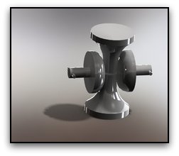
 The Warko transmission uses a series of progressively tapered cones surrounding the main drive shaft in order to create an incremetal change in gear ratios. The number of cones that surround the main drive shaft have a direct corrleation with the amount of torque that the system can hande. This makes for additional parts that can create complexities.